sivava willem pcb50b - defective board, wrong components

Ответить
someone
Сообщения:4
Зарегистрирован:Чт мар 07, 2013 2:45 pm
sivava willem pcb50b - defective board, wrong components

Сообщение someone » Чт мар 07, 2013 3:20 pm

I recently bought a sivava pcb 5.0b with software 98d12c4.

I can't get the programmer to read PLCC32 lpc/fwh bios chips correctly.
UPDATE: It works now and was a hardware issue, see later posts

Dumping an Arduino Uno R3 chip flash via SPI (ICSP) worked fine, as far as I know.

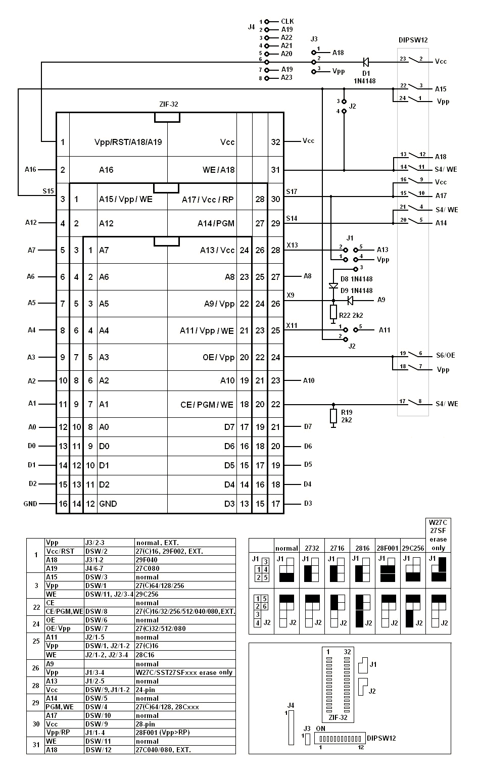
The chip jumpers are in standard configuration and set to 4.5 pbc mode (both configuration jumpers set left). The software is set to 5.0.

To address the usual problem sources:
- I'm using a hardware parallel port with ebc/epp capabilities
- I'm using an external 12V power supply capable of 1.5A current
- Dip switches were set accordingly to the software information.
- I used the appropriate LPC/FWH socket
- I have tried 4 chips of the SST49LF line and one PMC PM49LF.

SST 49LF004A is read as 0x00 / 0x00, SST 49LF004B is read as 0x04, 0x04 on the same settings, which is equal to the ID taken of thin air in the socket.

My problems seem identical to:
viewtopic.php?f=10&t=4795

The issues were symmetrical on the FWH port and on the ZIF socket I used for first multimeter tests.
To make sure that it's not a simple solder error, I went over some non-perfectly soldered component solder points and resoldered some of them. It made no difference.

I have checked the output voltages with a multimeter.
Some lines are strange. Should any line considerably differ from others?
Details
jupered to 5V VCC, 12.5V VPP, external power supply
1 - VPP: 13.60V
32 - VCC: 4.93V

Data lines not mentioned are on 4.26V high, 0V low.
anomalities:
29 - A9 - 2.8V high, 0V low
22 - CE - 1.01V high, 0V low

on the FWH header, #RST is held at 3.05V

the extension header with A19 to A22 seems fine, all 4.26V on high, Pin1 has VPP.

The same goes with #RST, you want to keep that pin high to avoid resets.
A9 is strange, but 2.8V should be enough to be HIGH on 3.6V devices.

I suspect the problem lies with 22 - #CE:
#CE seems to be named #WE (write enable) in chip datasheets and work as the switch of read / write operations, with LOW beeing write mode.
1.01V means that there is a problem bringing the chip to read mode if i'm correct.
I have traced the CE line to the CMOS Buffer TI CD4503BE E4 next to the VCC VPP lights in the lower left corner, it's Pin 11 or Q5 of the chip.
To ensure that the chip is not defective, I have switched it with its left twin, no change in output voltage, still 1.01V. But that makes no sense. The datasheet
http://www.ti.com/lit/ds/symlink/cd4503b.pdf
says its a non-inverting CMOS buffer, pin 11 is the Q5 "output", matching D5 "input" is right on pin 12 next to it. All other Q pins are on 4.26V if their D pin partner is at 3.3V, but with Q11, that's not the case.
Some futher search: #CE is directly linked to Dip switch 11 and goes up to 1.5V if Switch 11 is up. But only if 12 is up, too, otherwise it stays on 1.07V.
Playing with the dip switches brings the CE voltages up, but some configurations seem to produce a short circuit, causing the voltage regulator on the board to overheat. Ugly design.

Possible hardware issues:
One strange thing: two parts between the dip switch and the zif socket, which are not visible in this picture by lamer666, are missing. One is a 2k2 resistor, the other is a 4148 diode.
Изображение

Their positions appear to be empty in this picture from alibaba too:
Изображение
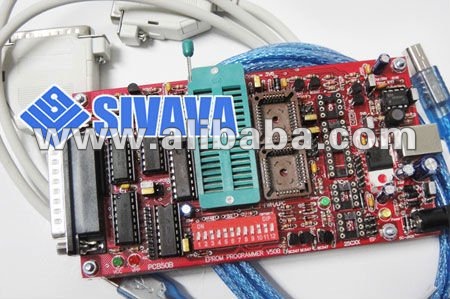
So it seems that that is not the source of the issues.

I really want to get this piece of hardware to work :wink:
Последний раз редактировалось someone Пн мар 11, 2013 1:17 am, всего редактировалось 2 раза.

Ezo
------
Сообщения:2042
Зарегистрирован:Пн янв 03, 2005 6:50 pm
Откуда:Riga

Re: sivava willem pcb50b PLCC32 problem: CE-22 voltage

Сообщение Ezo » Пт мар 08, 2013 2:51 am

22 - CE - 1.01V high, 0V low
1) Check/measure actual status of dipswitches 4 (off), 11(off), 8(on)
2) Test H/W. 22-CE on/off . Measure voltage changes 4503/12 and 4503/11 (bottom 4503)
Expect on both 4.3/0V. In case pin11 1.5V repeat test with all dipswitches off
Playing with the dip switches brings the CE voltages up, but some configurations seem to produce a short circuit,
Don't play with dip switches ! It can destroy programmer logic or target chip. Dipswitch understanding here
One strange thing: two parts between the dip switch and the zif socket, which are not visible in this picture by lamer666, are missing. One is a 2k2 resistor, the other is a 4148 diode.
That's normal.

someone
Сообщения:4
Зарегистрирован:Чт мар 07, 2013 2:45 pm

Re: sivava willem pcb50b PLCC32 problem: CE-22 voltage

Сообщение someone » Пт мар 08, 2013 1:16 pm

Thanks for the swift reply.

The complete lack of documentation by sivava makes everything complicated.

Did you mean with "Check/measure" that I should check if the dip switch bank itself is working correctly (having/not having a connection in on/off state)?
That is the case, I quickly checked: all on - all connected, all off - all disconnected. Interconnects are a different thing, though.

The dipswitch diagram hels a lot. That design is build for "cold configuration" while not connected to power, but the lack of a power switch (hard to build on the parallel port side, I guess) makes constant changes unplugging very impractical, leading to dangerous behaviour by the users.

With the schematics, I finally get why there has to be a 12pin dipswitch on the board - there are three different pincount format of eeproms on the ZIF socket, which are all incompatible power-distribution wise, because their designers thought it would be clever to put VCC and GND on opposite sides of the chip, making electrical compatibility between chip sockets impossible.
So you have to jumper those, and instead of having switches to select either line A or B to be on Pin X, the dipswitch bank doesn't stop you from setting line A to pin X AND line B to pin X at the same time.

Seeing that diagram, I really hope I haven't fried one of the ICs.
UPDATE: Spoiler warning-- they're all working well :D

The passive components look fine..Thankfully, having the pdip sockets allows easy replacements of the ICs. A good thing I didn't choose one of the chinese clones with SMD parts..

Dipswitch pins 4, 8 and 11 all get the same #WE (=CE) delivered and the configuration decides how it's distributed.

So on 8 on, 4+11 off, only the pin 22 of the ZIP socket should get the #WE signal, with a 2.2K pulldown resistor to ground applied. Is that correct?
I'm missing a parallel cable at the moment and will therefore measure the voltage later.

2.2k pulldown seems like a low figure if you want to read high voltages in the HIGH state on the pin. unfortunately, I can't measure if it's 2.2k in circuit. I'll check the rings ..

Update
What the hell? brown-grey-brown-gold = 180Ohm +-5% in the place of a 2.2k?
The pulldown resistor seems to be of the wrong resistance by a factor of 10.
I may be mistaken, but I have found 5 resistors of exactly that 180-ohm-kind on the board, and they all look WRONG:
- the 2k2k pulldown position, which is the only resistor between dip switch and zif socket, next to the empty positions I mentioned before: 180 ohms
- position next to the green led labeled "green", lower right part of the pcb, marker says 330 Ohm, is 180 Ohm
- upper right part of the pcb, marker says 330, is 180 Ohm
- upper right part of the pcb, marker says 1.2k, is 180 Ohm.
- ..

Now, either the markings on the pcb are all wrong and I traced the wrong pulldown resistor, or somebody just threw some random resistors at my board, with a low #WE voltage beeing only the most noticable outcome.
Can somebody look at his board and identify the 2k2 resistor value?

180 Ohms pulldown is a plausible explanation for the very low voltage on the #WE line. Who knows what the other wrong resistors do and if they are actually improvements over the marked values.

Update2
The capacitors seem weirldy switched, too. 47µF in the place where it says 22µF on the board, 22µF where it says 47µF.. I'll go and buy some replacements for the resistors and capacitors. But before I begin swapping parts, can somebody send me a high resolution photo of his working pbc 5.0 where I can identify the color codes on the resistors?
Последний раз редактировалось someone Пн мар 11, 2013 1:29 am, всего редактировалось 1 раз.

someone
Сообщения:4
Зарегистрирован:Чт мар 07, 2013 2:45 pm

Re: sivava willem pcb50b PLCC32 problem: CE-22 voltage

Сообщение someone » Сб мар 09, 2013 1:39 am

Anyway. Assuming that the printed values on the board are correct, I started swapping the parts for the correct values.
At the moment, I have counted 8 or 9 wrong resistors and all 4 of the electrolyte capacitors differ from their printed values (but only by a maximum factor of 2)

At the moment, I swapped those resistors which are off by a factor of 2 or more and one of the capacitors.

I'm unable to test the board until sunday, but I hope my "main" problems on #WE are gone now.
Последний раз редактировалось someone Пн мар 11, 2013 1:30 am, всего редактировалось 2 раза.

someone
Сообщения:4
Зарегистрирован:Чт мар 07, 2013 2:45 pm

Re: sivava willem pcb50b PLCC32 problem: wrong parts

Сообщение someone » Вс мар 10, 2013 7:11 pm

First test results.
The bad news: I still can't read the bios chips.
Their IDs are read as 0x00 or 0xFF, as well as all their data. (0xFF on the PMC ones)

Update: it works now! (see below)


The good news: exchanging the resistors helped a lot.

New values:
jupered to 5V VCC, 12.5V VPP, external power supply
1 - VPP: 13.57V
32 - VCC: 4.94V

Data lines not mentioned are on 4.28V high, 0V low.
These values are very similar to the ones before.

anomalities:
26 - A9 - 2.82V high, 0V low - still as before
22 - CE - 3.80V high, 0V low - fixed!

on the FWH header, #RST is held at 3.60V@5V VCC, 3.06V@3.6V.
VCC jumpered to 3.6V is nominal 3.40V (measured without current draw, will be lower during use, more like 3V).

Looks to me like the #WE mystery is solved, but I'm still missing something else..

One dead-end on my search for further manufacture errors was a 15k resistor (which is 15k by color code) that measured 0 Ohm, no visible reason why that is.
That line is going into the 34063A DC-DC Converter inverting input (pin 5).
As it turned out, the 12.75V - 21V jumper jumpered that one to 0 ohm if set to the 12.75V position, which is the default. Good thing I searched for more clues before replacing that resistor, as that would've been pointless.

I still had some "wrong" resistors on the board.

Particularly, one seemed critical:
it connects SCK (clock) on the ICSP header with the FWH socket and it is 180ohms, should be 330. On the FWH, it's not used for clocking though, its only FWH1.

I therefore swapped the remaining "wrong" resistors, three 180ohms, for the correct 330 ohm versions.

It seemed to me like "what could that small difference possibly change after all these other replacements" .. but it did change something. Or it didn't, and this other discovery of mine did:
VCC on the FWH header is 3.06V@3.6Vmode, 3.67V@5Vmode. (I assume the FWH socket is shifted down automatically, because no chip wants 5V VCC).
Important: It VCC on the FWH is NOT equal to the VCC on the ZIF socket, where most of the previous readings came from.

3.06V VCC at idle seems okay, but that dropped to about 2.9V during read attempts, which is probably not enough, and makes the difference to some of the IO lines even bigger, which is a bad thing. (Chips don't like voltage differences between VCC and IO, datasheets usually say more than 0.5V difference will kill it.)
It is necessary to set the 5V jumper if one wants to read a 3.6V chip in the FWH, which is totally counterintuitive and frankly pretty stupid, because if it would be 5V VCC as it said, the chip would not last very long :twisted:

The software didn't help either, because it is still riddled with all the wrong informations from to older pcb versions, like the graphics, so I had no confidence in that.

So, from here on I jumpered 5V for all the chip readings.

The first success was: I got the "SST49LF004A"-ID reading (0xBF man, 0x60 dev.) out of a SST49LF004B, the actual voltage during chip reading is 3.35-3.40V with 5V setting.

I selected SST49LF040 in the software because the SST49LF004B is a LPC and not a FWH like the SST49LF004A, as far as I recall.

SST49LF004B @ SST49LF040 settings : "slightly" wrong ID, reading works!

SST49LF004A: correct ID, reading works!

PMC49LF004: correct ID, reading works!

I haven't run a bitwise comparation to the bios ROM on the chips, but if strings and dates are correct in there, and they are, most of the other bytes will be too.
So I count that as a big success. I'll test the write operations tomorrow.

One quick side note: the actual CLK pin (pin 31 on the fwh header, according to sst datasheets) is hard wired to VCC. I'm not sure how that should make sense, but anyway, it works.

Ответить