|
|
-
carlos316
- Сообщения:13
- Зарегистрирован:Ср мар 14, 2012 1:41 am
Ezoser red led stays on always
Сообщение
carlos316 » Ср мар 14, 2012 2:01 am
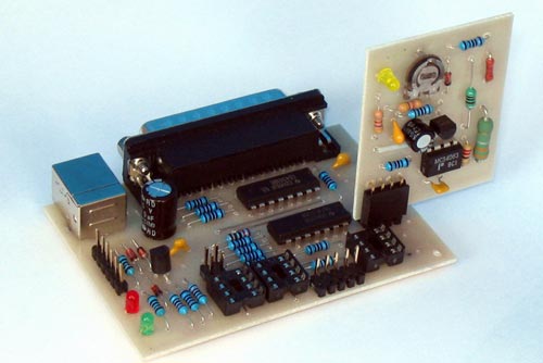
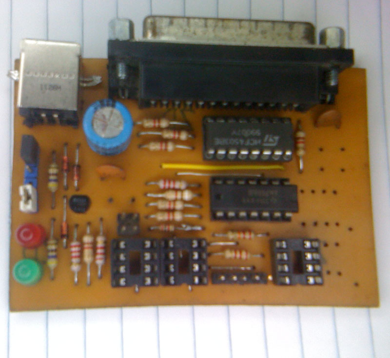 - upside board
- imagen arreglada1.jpg (114.56КБ)13742 просмотра
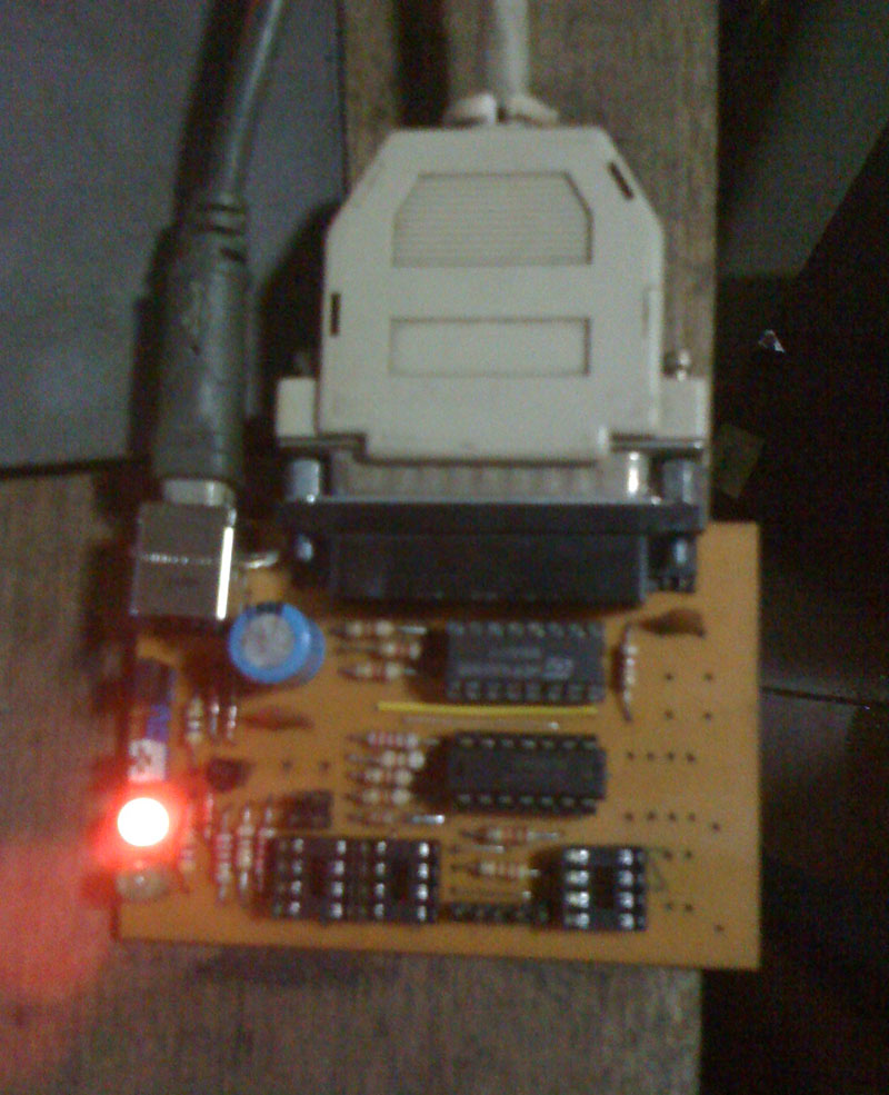
Hi Mr.Ezo i built the ezoser programer ,i finished but when i tried to use it the red led stays on ,i followed the sequence :
Connect LPT cable to PC and programmer.
Run Willem software.
Connect power supply to programmer.red led stays on (no flash just steady)
Run Willem SW command Help/Test Hardware(hardware error check connection)setup97ja
When run Sw test hardware Green led flash very fast once and gives me error massage
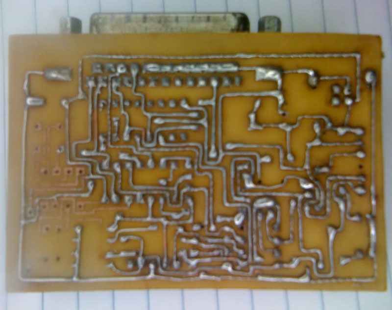
I checked all circuit thinking about a cut trace or maybe missing trace.everything is ok I checked the cable from lpt too and Lpt is standart on my bios win xp .
Is there any guide for ezoser ? or maybe a tip or something that guides me .
I'm building ezoflash 4.3 version but now need to program spi 25128-25256 eeproms ,wanna make work ezoser 1st and then continue with the other programer.
I wait for your answer Mr Ezo.
-
Вложения
-
 - imagen arreglada 5.jpg (173.58КБ)13742 просмотра
-
 - imagen arreglada 3.jpg (114.87КБ)13742 просмотра
-
Ezo
- ------
- Сообщения:2042
- Зарегистрирован:Пн янв 03, 2005 6:50 pm
- Откуда:Riga
Сообщение
Ezo » Сб мар 17, 2012 8:13 am
Connect power supply to programmer.red led stays on
Thats OK. USB is power source.
When run Sw test hardware Green led flash very fast once and gives me error massage
Error message "Check power and connections" - here is somewhere problem.
Green led flash may initially confirm - LPT port and cable OK.
Is there any guide for ezoser ?
1) check used LPT port (LPT1)
2) check parallel port cable (extension 1:1)
3) go in SW Test H/W (frame in SW below), set Jp1, Jp3 (5V)
a) activate 32-Vcc , it should turn green LED on
having a multimeter and schematic , and 32-Vcc on/off
measure voltage changes BU1/16, IC2 74LS06/5 (>3V/0), IC2/6 (0/5), V1E (5V), V1K (5/0)
socket 25xxx / 8, 7, 3 (5/0)
No voltage on 25xxx /7, 3 check pcb mod. Initial pcb have missing bridge between contacts IC3/3 and R16.
b) activate 24-OE, 32-Vcc, 13-D0 on/off
measure voltage changes BU1/2, IC2/1 (>3/0), BU1/11, IC2/10 (5/0) , IC2/2, IC2/8 (0/5)
socket 25xxx / 5 (0/5)
c) activate 24-OE, 14-D1 on/off
measure voltage changes BU1/3, IC1 4503/14, IC1/13 (5/0)
socket 25xxx / 6 (5/0)
d) activate 22-CE on/off
measure voltage changes BU1/17, IC1 4503/12, IC1/11 (5/0)
socket 25xxx / 1 (5/0)
I checked all circuit thinking about a cut trace or maybe missing trace
Note , initial PCB has missing trace between 25xxx / 3 and R16 (find resistor contactpad alone) - just place solder between contactpads.
I'm building ezoflash 4.3 version
I recomend ezoflash 4v5 , it support both paralel and serial devices
-
carlos316
- Сообщения:13
- Зарегистрирован:Ср мар 14, 2012 1:41 am
Сообщение
carlos316 » Сб мар 17, 2012 5:00 pm
Tnx for anwser Mr.Ezo I checked all the info you posted and those are the results:
1) check used LPT port (LPT1) Ok
2) check parallel port cable (extension 1:1) Ok
3) go in SW Test H/W (frame in SW below), set Jp1, Jp3 (5V) Ok
a) activate 32-Vcc , it should turn green LED on
having a multimeter and schematic , and 32-Vcc on/off Mismatch
measure voltage changes BU1/16, IC2 74LS06/5 (>3V/0), IC2/6 (0/5), V1E (5V), V1K (5/0)
socket 25xxx / 8, 7, 3 (5/0)
V1k (5/0) my test (5/0.99) less that 0 i think might work the rest measures are all Ok
b) activate 24-OE, 32-Vcc, 13-D0 on/off Error
measure voltage changes BU1/2, IC2/1 (>3/0), BU1/11, IC2/10 (5/0) , IC2/2, IC2/8 (0/5)
socket 25xxx / 5 (0/5)
the only problem i found was IC2/8 (0/0) when 13-DO switch no voltage change keeps 0/0
c) activate 24-OE, 14-D1 on/off Ok
measure voltage changes BU1/3, IC1 4503/14, IC1/13 (5/0)
socket 25xxx / 6 (5/0)
d) activate 22-CE on/off Ok
measure voltage changes BU1/17, IC1 4503/12, IC1/11 (5/0)
socket 25xxx / 1 (5/0)
Mr.Ezo all voltages and changes are ok the only error i found was IC2/8 that dont switch the voltage , i changed 274LS06 (tried with 2 more)but same error any idea what could be wrong .
I have a doubt if 74S04 can work the same way 74LS06 both are hex inverters same pin configuration
-
Ezo
- ------
- Сообщения:2042
- Зарегистрирован:Пн янв 03, 2005 6:50 pm
- Откуда:Riga
Сообщение
Ezo » Сб мар 17, 2012 5:56 pm
b) activate 24-OE, 32-Vcc, 13-D0 on/off Error
measure voltage changes BU1/2, IC2/1 (>3/0), BU1/11, IC2/10 (5/0) , IC2/2, IC2/8 (0/5)
socket 25xxx / 5 (0/5)
the only problem i found was IC2/8 (0/0) when 13-DO switch no voltage change keeps 0/0
See schematic. D0 is running from D00 (BU1/2) through 4 logic elements back to BU1/11.
Now changes stops at IC2/8 . Last checked controlpoint IC2/10.
Run same test and check again IC2/10 (5/0), IC2/9 (5/0), IC2/8 (0/5), IC2/3 (0/5), IC2/4 (5/0), BU1/11 (5/0)
Check - are resistors R11 and R14 getting Vcc2 (+5)
No changes at IC2/9- check line from IC2/10 to R12 to IC2/9 (no shorts or line breaks)
No changes at IC2/8 - check line from IC2/8 to IC2/3 and R14 (no shorts or line breaks)
....
i changed 274LS06 (tried with 2 more)but same error any idea what could be wrong .
Logic usually works, 99% of problems are contacts
I have a doubt if 74S04 can work the same way 74LS06 both are hex inverters same pin configuration
Apply 74LS06
-
carlos316
- Сообщения:13
- Зарегистрирован:Ср мар 14, 2012 1:41 am
Сообщение
carlos316 » Сб мар 17, 2012 7:54 pm
Ok Mr.Ezo I check again and these are the results:
See schematic. D0 is running from D00 (BU1/2) through 4 logic elements back to BU1/11.
Now changes stops at IC2/8 . Last checked controlpoint IC2/10.
Run same test and check again IC2/10 (5/0), IC2/9 (5/0), IC2/8 (0/5), IC2/3 (0/5), IC2/4 (5/0), BU1/11 (5/0)
My test IC2/10(5/0) Ok , IC2/9(5/1.5v)mismatchIC2/8(0/0)Mismatch,IC2/3(0/0)mismatch,IC2/4(5/5)mismatchalways 5v no switch,BU1/11(5/0) Ok
Check - are resistors R11 and R14 getting Vcc2 (+5) OK OK
No changes at IC2/9- check line from IC2/10 to R12 to IC2/9 (no shorts or line breaks) OK,OK
No changes at IC2/8 - check line from IC2/8 to IC2/3 and R14 (no shorts or line breaks)Ok,OK
I unsolder R14 from pin 8 /IC2 ,I have 4.8V ,switched but when conect to pin IC2/8 voltage drops.
I'm still stuck with the programer
-
Ezo
- ------
- Сообщения:2042
- Зарегистрирован:Пн янв 03, 2005 6:50 pm
- Откуда:Riga
Сообщение
Ezo » Сб мар 17, 2012 10:12 pm
IC2/9(5/1.5v)
Replace resistor R12 22k with 2k2, resistor R13 2k with 100 Ohm.
Repeat test and measurements starting from IC2/10.
-
carlos316
- Сообщения:13
- Зарегистрирован:Ср мар 14, 2012 1:41 am
Сообщение
carlos316 » Сб мар 17, 2012 11:30 pm
Yeahhhhhhhhhhhhhh succed many thanks Mr.Ezo the changes made the difference :
Replace R12 22k to 2.2k and R13 2K to 100 now IC2/8 (0/5) ,and software "Hardware Present" every thing you pointed was right ,so its means the schematic must be corrected to those changes right.
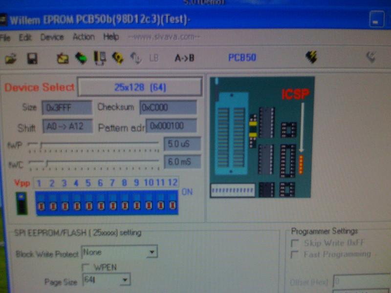
Now just have question about programming 25128-25256 spi Ezoser only have 5 jumpers ,How do i have to configurate them to read and write those spi.
Willem soft shows 12 jumpers how i know which jumpers should i use
-
Вложения
-
 - Hardware Present Now
- IMG_0389.jpg (52.52КБ)13694 просмотра
-
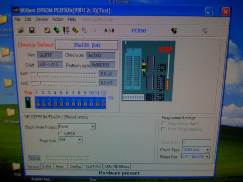 - 25128 Settings
- IMG_0390.jpg (59.54КБ)13694 просмотра
-
Ezo
- ------
- Сообщения:2042
- Зарегистрирован:Пн янв 03, 2005 6:50 pm
- Откуда:Riga
Сообщение
Ezo » Вс мар 18, 2012 7:24 am
so its means the schematic must be corrected to those changes right.
EZoSer was my experimental board to manage /create serial part based on 74LS06 for latest programmer 4v5. Resistors were changed in 4v5. Another change to improve signals timing issues for particular chips - D0 pass one 4503 buffer before IC2/1. Find changes in attached file. Vpp part with MAX662 not used.
Not necessary to create last change if ezoser is running on your chips.
Btw what is exact your IC2 chip type , 74LS06 or different ?
How do i have to configurate them to read and write those spi.
Willem soft shows 12 jumpers how i know which jumpers should i use
It's easy - set correct voltage with jumpers Jp1, Jp2, Jp3 (equal to 4v4/4v5) only.
Your chips have wide voltage range - check in chip database, enter 25128, select chip, look to data and link to datasheet.
I recomend to start with voltage 3.6V by default (set Jp2) for all serial chips.
If datasheet confirm chip 5V only, then change jumpers to 5.0 (Jp1,Jp3) or 4.3 (Jp3)
For SPI flash chips sometimes less voltage required 2.9V (no jumpers Jp1-3) or 3.6V (Jp3) with best voltage levels compatibility (all signals and power within chip voltage range 2.7-3.6).
Other jumpers Jp4 and Jp5 usually removed . Apply for chips 93C/CS to select 8 or 16bit mode (ORG), to enable programming (PRE).
-
Вложения
-
- ezoser_mod.zip
- (88.34КБ)485 скачиваний
-
carlos316
- Сообщения:13
- Зарегистрирован:Ср мар 14, 2012 1:41 am
Сообщение
carlos316 » Вс мар 18, 2012 3:33 pm
Hi again Mr.Ezo " Btw what is exact your IC2 chip type , 74LS06 or different ? " ok ,the IC2 chip that i'm using is SN7406 ,its from a fake brand dunno if meets all the specification but now works.
I read and write differents 25128-25256-25512 already ,I havent tried with 24CXXX but I guess its gonna work too running 98D12C3 sw and ezoser works amazing .
The ezoser is working 100% now and helps me to do what i need but ,i just wanna know which was the use of that part of the circuit " Vpp part with MAX662 not used." and i saw in another post viewtopic.php?f=3&t=2399 EZoSer this mod ,i'm just courious about it.
Anyway i cant find that max662 in my country and i'm just courious about it use.
"I recomend to start with voltage 3.6V by default (set Jp2) for all serial chips." that set of jumpers work ok for me fast read and fast write .
I need to program AT49LV001N tsop32 chip ,now im finishing the ezoflash 4.4 version just need to add a few more parts and build the tsop adapter when finish I'll post the pics and hope not to have problems with it ,but if that happends i count with you help.
I'm not that good with pcb's thats why i didnt try with 4.5 version double side pcb kills me ,and in my place i cant find photoresist spray .so the iron toner is my choise.
Mr.Ezo I wanna thank you for your time ,been patient ,the fast answer and for sharing your knowledge and very specially for your greats programers which made our lives easier.
-
Вложения
-
 - Shaper-Vpp_FOTO1.jpg (26.9КБ)13688 просмотров
-
Ezo
- ------
- Сообщения:2042
- Зарегистрирован:Пн янв 03, 2005 6:50 pm
- Откуда:Riga
Сообщение
Ezo » Вс мар 18, 2012 4:53 pm
The ezoser is working 100% now and helps me to do what i need but ,i just wanna know which was the use of that part of the circuit " Vpp part with MAX662 not used." and i saw in another post viewtopic.php?f=3&t=2399 EZoSer this mod ,i'm just courious about it.
Vpp part is designed for PIC programming. This part in ezoser not approved, generic solution used in ezo4v5. My projects are open, here is a lot of individual mod's.
ok ,the IC2 chip that i'm using is SN7406 ,its from a fake brand dunno if meets all the specification but now works.
I recomend find and apply 74LS06 in future , not all chips may accept 7406.
I need to program AT49LV001N tsop32 chip ,now im finishing the ezoflash 4.4 version just need to add a few more parts and build the tsop adapter when finish I'll post the pics and hope not to have problems with it ,but if that happends i count with you help.
Hope in good results 
I'm not that good with pcb's thats why i didnt try with 4.5 version double side pcb kills me ,and in my place i cant find photoresist spray .so the iron toner is my choise.
Comercial empty boards are available.
|
|