Willem programmer software version 0.97ja
Programmer jumpers - W/Jp1- wire cable to dc2dc_a4, Jp3 (+5V), Jp5 (A18)
27C400, 27C800, 27C160
Selected device EPROM > 27Cxxx > M27C400, M27C800, M27C160, twp=140mks
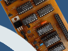
DIP-42_A1 jumpers A, C
dc2dc_a4 jumpers
JpR (Vcc from LM317), JpM (Vcc=5.8V) , JpP (Vpp=11..14V), JpT (BYTE# log1, chip 16bit mode)
Adjust R5 - Vpp=12.8V
Socket pins 1 and 42 are not used for chip 27C400 in DIP-40 package.
Verified chip - M27C160
27C322
Selected device EPROM > 27Cxxx > M27C322, twp=140mks
DIP-42_A1 jumpers B, D
dc2dc_a4 jumpers JpR (Vcc from LM317), JpM (Vcc=5.8V) , JpP (Vpp=11..14V).
Adjust R5 - Vpp=12.1V
Verified chip - M27C322
Chip test results find in chip_test.xls file.
Adjust other Vpp value or change Vcc=6.2V (jumper N), change twp, if required from EPROM datasheets or programming fail.
Chip read available without dc2dc_a4, some can be programmed with Vcc=5V, Vpp=12, set jumpers JpK, JpL.
dc2dc and dc2dc_a2 cant be used with dip42_a1, chip in 8 bit mode (BYTE-low, Vpp-off).
How to adjust Vpp ?
Install dc2dc_a4 and eprom adapter without target chip on ezoflash+.
Connect power supply, PC and run SW. Adjust Vpp on LM317- IN with R5
Only erased EPROM can be programmed. Initially, and after each erasure, all bits of the EPROM are in the logic high state. Run SW command Blank check to assure all bytes are 0xFF.
Logic lows are programmed into desired locations. Repeat programming (check voltage, increase twp) on logic low programming failure.
Programmed logic low can be erased only by ultraviolet light (UV lamp , wavelenght 2537 Angstroms, intensity 12mW/cm2, chip window 1..2cm from UV source, exposure time 12
20 minutes).
Chips without window are OTP (one time programmable) and cannot be erased.
Report problems and share your experience on Willem and EZoFlash forums.

 |
|


|
|
DIP-42_A1
Settings, verified chip list and info.